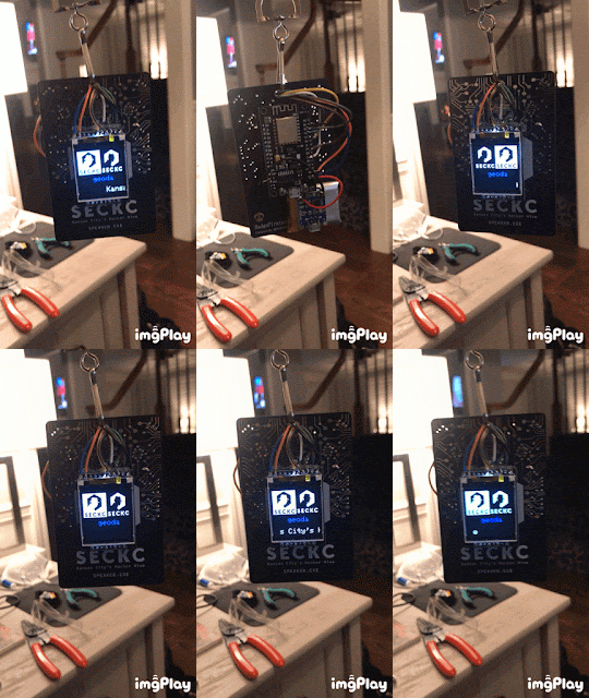
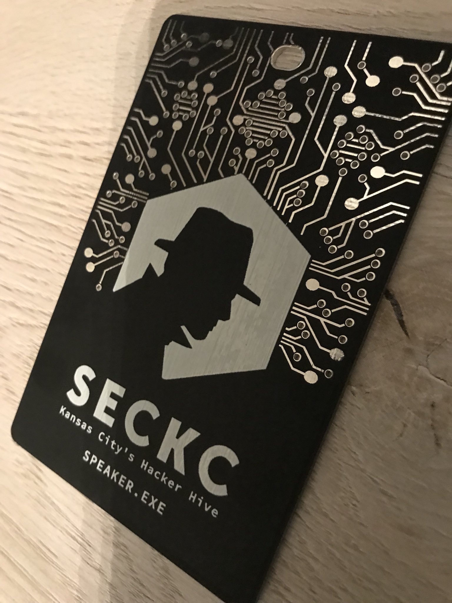
As you can tell, the original speaker badge is amazing on its own. However, I wanted to take it a bit further and customize it with my handle and thought a digital display would look awesome!
To begin, I had very little experience with electronics. While I have done a few "blinky" LED kits requiring soldering, I have not really messed with anything further. Prior to this project I did have to pick up a lot of tools. Below is a list of items that were either required or very helpful with this project:
- Soldering Iron (required)
- Soldering wire (required)
- Jumper Wire/Connectors (required)
- Pliers (required)
- Wire cutters (required)
- Hot glue gun (required)
- Double sided padded tape (required)
- Helping Hands (extremely helpful, if not required)
- Breadboard (extremely helpful, it not required)
- Solder sucker (helpful)
- PCB connectors (helpful)
- Flux (extremely helpful, if not required)
 |
| Left: NodeMCU board, Top: TP4056 board, Right: 1.44" TFT SPI LCD |
 |
| Same as above but turned over |
With these pieces in hand, I followed the documentation to hook up the LCD and the development board with jumper wires.
After connecting the display to the board, I then loaded up Arduino IDE. I set the board manager to ESP8266 and chose the NodeMCU 1.0 (ESP-12E Module). I then installed the Adafruit-GFX-Library and Adafruit-ST7735-Library. I chose the ST7735 example "graphicstest" and updated the following code to correctly display on the TFT:
#define TFT_CS        D1
#define TFT_RST       D2
#define TFT_DC        D3
#define TFT_MOSI      D7
#define TFT_SCLK      D5
 |
| Display successfully works! |
**Update** Code is currently on my github and SecKC's github.
For the prototype, I wanted it to be simple:
- Have the SecKC logo (black and white)
- Have my handle (different color)
- Have scrolling text
**Update** I have made modifications to the code to include pictures such as Avatar, SecKC artwork and some simple animation loops.
Again, this is only a prototype and I will be updating the code in the future to have more, such as a full image display of my avatar, the SecKC logo and much more.
For the Logo:
I first downloaded a SecKC image, resized it to the appropriate pixel size (64x64) and converted it to a hexadecimal matrix. The converted image also has an inverse (Black/White vs White/Black). I printed these images to the screen in the top left and the top right corners of the display. I have a loop set up that will swap the images after X seconds.
For the Handle:
I knew it was going to be a static text. I plotted the location that I wanted the handle to be printed and I made sure that it was displayed prior to the loop. This way it saves some refresh and display time.
For the Scrolling Text:
The loop was fairly simple since I basically just plotted the location of the text and iterated through the letters in a right to left fashion. I have it set up with common SecKC lingo such as "HAKCER" and "Kansas City's Hacker Hive". I will add more in the future.
With the prototype code complete, I pushed it to the display and tested:
 |
| Code successfully uploaded |
Next, I needed to decide how I wanted the wiring to be done. One option was to cut into the center of the badge and create a large enough gap to stuff the wires through the badge and out the other end. Another option was to have the display at the top of the badge and just run the wires directly behind it. These 2 options did not require soldering since I could just directly connect the jumper wires to the back of the display. However, the last option and the one I decided on, was to mount the display onto the center of the board, solder the wires onto the front of the LCD and have the wires route through the lanyard hole into the back.
Additionally, I did not want to fully cover the SecKC logo that was originally on the badge. I accomplished this by utilizing a GPIO connector and cutting off the male pins, causing the LCD to be raised from the badge. At the beginning, I pulled out every pin of the connector. But I soon realized the pins were necessary in order for the LCD pins to actually "lock" into the connector. I ended up just bending off the pins and ripping the top part out and leaving the inside pins. This would allow the connector to be smooth as I glued it to the front of the badge. I then cut the connector to length and used super glue to glue the LCD to the badge.
 |
| Cut connectors to length and trimmed male pins |
 |
| LCD attached to connector which I glued to front of board |
With the LCD mounted on top, I then ran the wires through the lanyard hole at the top.
 |
| Wire jumper wires through lanyard hole |
**UPDATE**: So, it turns out that I didn't know how to tin a wire. I was under the assumption that you could simply heat the wire and add solder. While that is true, it is 100% easier/smarter/better to use flux when tinning a wire. This allows the bonding of the wires to work a lot better, plus it's a lot easier to connect the wires to the pins. When I did this, it made my life a lot easier.
 |
| Jumper wires successfully soldered to front LCD |
 |
| Other end of jumper wire directly connected to board confirming display works |
With the front complete, it was time to do the back. For the back, I wasn't too concerned about how it looked. I decided to buy a mini sticky breadboard and attach the ESP8266 NodeMCU to the breadboard and just stick it to the back. With the board connected, I stripped off the other end of the jumper wires, tinned and soldered them to the front of the ESP8266 NodeMCU:
 |
| Back of Badge. Jumper wires soldered to ESP8266 NodeMCU |
 |
| Side angle of Badge |
 |
| Front of Badge |
Now that I have the LCD screen mounted on the front of the badge, wires connected to the ESP8266 NodeMCU that is mounted on the back of the badge, it was now time to add the battery. With the help of friend (Thanks Bill! who soldered the TP4056 to the battery), I used double sided padded tape to stick the battery to the back of the badge. I then soldered the positive and ground wires of the TP4056 to the badge and completed the badge!
 |
| Badge Complete |
Considering this was my first true hardware hacking project, I was very satisfied with the results. I still have a lot of work to do with soldering and learning different techniques. Ultimately, I looked at this first project as a badge prototype and will look into making more in the future! Who knows, maybe I'll even make a custom circuit board?
I hope this has been informative and motivating for those who have not done any of this before. If I can do it, anyone can! Good luck and happy hacking!
Until next time.
***Note***
I still have much I want to do and hopefully will get around to it soon:
- Shorten the length of the wires, thus cleaning it up and making it look better (complete)
- Use better wires and have better soldering points (complete)
- Add more to the badge (avatar, large SecKC logo, more scrolling text, etc) (complete / work in progress)
- Find smaller/cheaper parts for this same project (maybe to make more for fellow SecKC'ers?) (in progress)


